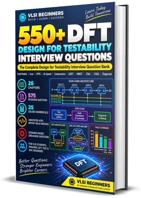
90+ free Design for Testability questions, from fault models and scan to compression, BIST, JTAG and first-silicon debugging. Includes 18 worked answers, 8 solved numericals, an ATPG coverage-report walkthrough and a scan test-time calculator.
575 questions with interview-ready answers and tips, 25 solved numericals, an annotated ATPG report and 30 debugging scenarios.
DFT interviews ask a different question from design interviews: not "does the chip work?", but "can we prove every manufactured chip works, quickly and cheaply?" That's why they mix concepts with numbers. You'll be asked to compute a test time, explain why coverage is stuck, or say what to check when the scan chain fails on every die.
This page is built around that. Start with the formula sheet and the calculator, browse 50 questions across ten topics, then work through the worked answers, numericals and the ATPG report walkthrough. Try each one aloud before opening the answer.
Fault models, scan flops, shift and capture, ATPG, test vs fault coverage, and usually a calculation: test time, coverage from fault classes, or collapsed fault counts.
LOC vs LOS and the OCC, how compression works and why X-values hurt it, LBIST and MBIST, the JTAG TAP, IJTAG and core wrappers. Expect to draw at least one block diagram.
Common from 2–3 years of experience: coverage stuck below target, chains failing on first silicon, at-speed fails, pattern simulation mismatches, test time over budget.
"Scan turns a sequential ATPG problem into a combinational one" says more than any definition. Interviewers listen for the why behind scan, OCCs, lock-up latches and wrappers.
A mux-D scan flop, the shift/capture waveform, LOC vs LOS, PRPG → chains → MISR, the TAP state machine. A quick sketch earns full marks fast.
Test coverage and fault coverage have different denominators, and collapsed and uncollapsed counts differ. Name the definition before you quote a number.
Test time, tester memory, multi-site, overkill vs escapes, DPPM. Tying a DFT choice to cost and quality signals production maturity.
Uninitialised memories, black boxes, non-scan flops and bus contention create X. Mention how they hurt coverage, compression and LBIST, and how you'd bound them.
All dies fail or some? Chain or logic? Stuck-at or at-speed only? Classify, verify the setup, isolate, find the root cause, then re-verify across modes and corners.
P = patterns, L = longest chain, C = capture cycles per pattern, PD credit is usually 50%.
Set internal chains equal to channels for plain scan; raise it to see what compression does.
| FAULT MODEL | PATTERNS | SPEED | TARGETS | TYPICAL USE |
|---|---|---|---|---|
| Stuck-at | 1 (load, capture) | Slow | Node fixed at 0 or 1 | Baseline production test |
| Transition | 2 (launch, capture) | At-speed | Slow-to-rise / slow-to-fall | Delay defects, LOC/LOS |
| Path delay | 2 | At-speed | Specific critical paths | Speed paths, binning |
| Small delay | 2, timing-aware | At-speed | Longest path through each fault | Quality at advanced nodes |
| Bridging | 1+ | Slow | Shorts between layout neighbours | Defect-oriented test |
| Cell-aware | 1 or 2 | Slow or at-speed | Defects inside standard cells | DPPM reduction, automotive |
| IDDQ | A few vectors | Measured | Leakage defects | Bridges, oxide defects |
A sample of what interviewers draw from most. The full 575-question ebook covers each topic in much more depth, with every question answered.
Why manufacturing test exists and what it measures.
How real defects are abstracted for ATPG.
Making every flop controllable and observable.
Generating patterns and proving how good they are.
Catching delay defects with a slow tester.
Cutting test time and tester memory by 10–100×.
Letting the chip test itself.
Standard ways to reach test logic.
Where DFT meets STA and physical design.
What happens after the patterns reach the tester.
575 questions across 26 chapters, all answered: 25 solved numericals, an annotated ATPG report, 30 debugging scenarios, plus IJTAG, hierarchical DFT, diagnosis and automotive test.
Try each one out loud first, then open it. Every answer shows what a strong reply covers, what the interviewer is really listening for, and the mistake that costs candidates the most.
Verification asks whether the design is correct: does the RTL do what the spec says? It's done once, before tape-out. Manufacturing test asks whether each fabricated chip matches the design: did a particle, short or open break this particular die? It runs on every chip, on a tester, in seconds.
Design for Testability adds structures that make that test possible and cheap: scan chains so every flop can be set and read, ATPG patterns, compression to cut tester time, BIST for memories and logic, and JTAG for access.
The goal is high defect coverage at low test cost: few escapes (bad chips shipped, measured in DPPM) and little overkill (good chips rejected).
A stuck-at fault assumes one node is permanently tied to 0 (SA0) or 1 (SA1). Every pin has two such faults. To detect one, ATPG must excite it (drive the node to the opposite value) and propagate the difference to an observable point by setting side inputs to non-controlling values.
Real defects are shorts, opens and resistive vias, not perfect stuck nodes. Stuck-at is still the baseline because it's simple, scales to billions of faults, and patterns that detect all stuck-at faults also catch a large share of real defects. Transition, cell-aware and bridging models are added on top for what it misses.
Fault lists are collapsed: an n-input AND/NAND/OR/NOR gate has 2(n+1) faults, collapsing to n + 2.
Each flop is replaced by a mux-D scan flop: a 2:1 mux in front of D selects functional data when scan enable (SE) = 0 and the scan input (SI) when SE = 1. Flops are stitched SO → SI into chains between scan-in and scan-out pins.
This makes every flop a pseudo-input and pseudo-output, so ATPG only has to solve combinational logic between flops.
Controllability is how easily a node can be set to 0 or 1 from the inputs. Observability is how easily its value can be seen at an output. A node deep in a 16-input AND tree is hard to set to 1 (all inputs must be 1); a node feeding only a long chain of logic is hard to observe.
Scan makes every flop fully controllable and observable. Inside combinational logic, test points fix what's left: a control point (an OR/AND gate with a test-only input) forces a hard node, and an observe point (a scan flop tapping the node) captures it directly.
Test points matter most for LBIST, where random patterns rarely hit hard-to-control nodes, but they also cut deterministic pattern counts.
Fault coverage = (DT + 0.5·PD) / all faults Test coverage = (DT + 0.5·PD) / (all faults − UD)
Both count detected faults (DT) plus partial credit for possibly detected faults (PD, where the faulty value is X at the observation point). Test coverage removes faults proven undetectable (unused, tied, blocked, redundant) from the denominator, because no pattern could ever detect them. So test coverage is always ≥ fault coverage.
Most teams sign off on test coverage, but you should always say which one, and whether the fault list is collapsed or uncollapsed, because the numbers differ.
A transition fault models a node that is slow to rise or slow to fall: the logic value is right, but it arrives too late. Resistive vias, weak transistors and small bridges cause this, and stuck-at patterns applied at slow tester speed can't see it.
Detection needs two patterns: the first sets the node to the initial value, the second launches the transition, and the response is captured exactly one functional clock period later. If the transition didn't arrive in time, the wrong value is captured.
Because the tester's own clock is slow and noisy, the launch and capture pulses are usually generated on-chip by an OCC from the PLL.
Both launch a transition and capture it one functional period later. They differ in how the launch happens:
The on-chip clock controller passes the slow tester shift clock during shift, then gates exactly two (or more) PLL pulses for capture, glitch-free and synchronised to SE. Most designs use LOC with OCCs.
A typical ATPG pattern needs only a few percent of its scan bits to be specific values (care bits); the rest are don't-care. Compression exploits that:
Short chains mean far fewer shift cycles per pattern, so test time and data volume drop 10–100×, even if pattern count rises.
X-values are the problem: one unknown bit entering an XOR compactor corrupts every output it combines with, hiding real fault effects. Designs fix X at the source (bound memories, initialise flops) and use X-masking to block X chains per pattern.
An X-source is anything whose value ATPG can't predict in test mode:
Fixes: bound them with test-mode logic that forces a known value (an AND/OR gate driven by test mode), wrap memories with scannable collars or use memory models, make or initialise the flops, add X-masking in the compactor, and mark at-speed paths that aren't valid so their captures are masked.
In the common STUMPS architecture, a PRPG (an LFSR plus a phase shifter) feeds pseudo-random data into the scan chains, the chains capture, and a MISR compacts all chain outputs into one signature. A controller sequences shift and capture and compares the final signature with the golden value, reporting pass/fail through JTAG or IJTAG.
There's no tester to mask anything, so a single X anywhere corrupts the whole signature. The circuit under test must be fully X-bounded.
Random patterns also struggle with random-pattern-resistant faults: an output of a 10-input AND needs all inputs at 1, probability 1/1,024 per pattern. Test points raise those probabilities. LBIST is popular for in-system test in automotive designs (ISO 26262).
Embedded memories are too dense and too numerous to test with scan, so each gets MBIST: a controller and a collar that run March algorithms at speed. March C− (10N):
⇕(w0); ⇑(r0,w1); ⇑(r1,w0); ⇓(r0,w1); ⇓(r1,w0); ⇕(r0)
It catches stuck-at, transition, address-decoder and many coupling faults; running both address directions is what catches coupling between cells.
Repair: memories have spare rows or columns. BIRA (built-in redundancy analysis) decides which spares cover the failing cells; the result is stored in eFuses. At every power-up, the repair data is loaded into the memories (BISR) before use.
IEEE 1149.1 (JTAG) defines a test access port with TCK, TMS, TDI, TDO and optional TRST*, a 16-state TAP controller, an instruction register and data registers. The boundary-scan register sits on every I/O so board interconnects can be tested. Mandatory instructions: BYPASS (a 1-bit register, opcode all 1s), SAMPLE/PRELOAD and EXTEST. Holding TMS = 1 for five TCK cycles resets the TAP from any state.
IEEE 1687 (IJTAG) extends access to hundreds of on-chip instruments (MBIST controllers, sensors, PLL controls) through a reconfigurable network of SIBs and test data registers, described in ICL and driven by PDL that tools retarget to the chip pins.
IEEE 1500 wraps embedded cores with a wrapper boundary register, so each core can be tested in isolation (INTEST) and its surroundings tested from outside (EXTEST).
Every die failing means a systematic problem, not random defects. Suspect the setup and the design first:
Then compare the tester log with a simulation of the exact tester pattern.
A problem specific to that chain's implementation, not the overall setup:
Check test-mode STA for shift on that chain, simulate shift with SDF, and run chain diagnosis on the fail data to locate the failing cell. The 0011 chain-test pattern shows whether it's stuck, slow-to-rise/fall, or a hold-type "jump".
A fail rate that high is rarely real delay defects. Check the test before blaming the silicon:
Zero-delay simulation checks logic only; SDF simulation adds real timing, so the failures are timing problems in test mode:
Check test-mode STA for the failing endpoints, confirm the SDF corner matches, and check whether those captures should be masked. Fix the design or the constraints, not the expected values.
Start with where the time goes (shift cycles, pattern count, MBIST, other tests), then rank options by gain and cost:
Then re-check coverage and power for every change.
DFT interviews regularly include quick calculations. Work each one on paper first, then tap to check.
L = 240,000 / 24 = 10,000
Cycles ≈ (2,500 + 1) × 10,000 + 2,500 × 1
= 25,012,500
Time = 25,012,500 × 40 ns ≈ 1.0 sNote: the "+1" is the final unload; every other unload overlaps the next load.
L = 240,000 / 1,200 = 200 Cycles ≈ 5,001 × 200 + 5,000 = 1,005,200 Time = 1,005,200 × 40 ns ≈ 40.2 ms Gain ≈ 1.0 s / 40.2 ms ≈ 25×
Note: twice the patterns, 25× less time. Compression cuts cycles per pattern, not patterns.
Credited = 75,600 + 0.5 × 600 = 75,900 Test cov = 75,900 / (80,000 − 2,000) = 97.31% Fault cov = 75,900 / 80,000 = 94.88%
Note: test coverage is higher because undetectable faults leave the denominator.
DL = 1 − Y^(1−T) T = 0.99 : 1 − 0.8^0.01 ≈ 0.00223 → ≈ 2,230 DPPM T = 0.999: 1 − 0.8^0.001 ≈ 0.00022 → ≈ 223 DPPM
Note: 0.9% more coverage cuts escapes about 10×. That's the business case for the last fraction of a percent.
Q1+ = Q1 ⊕ Q3, Q2+ = Q1, Q3+ = Q2 001 → 100 → 110 → 111 → 011 → 101 → 010 → 001
Note: 7 distinct non-zero states = 2³ − 1, so yes. All-zero is excluded: an XOR-feedback LFSR would stay at 000 forever.
N = 262,144 words March C− : 10N = 2,621,440 × 2 ns ≈ 5.24 ms MATS+ : 5N = 1,310,720 × 2 ns ≈ 2.62 ms
Note: complexity counts word operations, not bits; word width doesn't change it.
IR length = 5 + 4 + 6 = 15 bits DR length = 1 + 250 + 1 = 252 bits
Note: each BYPASS register is 1 bit. That's exactly why BYPASS exists: to keep the chain short when you only talk to one device.
p = 2^−8 = 1/256 per pattern N ≥ ln(0.01) / ln(1 − 1/256) ≈ −4.605 / −0.00391 ≈ 1,177 patterns
Note: at 16 inputs, p = 1/65,536 and N grows to about 300,000. That's why LBIST needs control test points.
"Here's our ATPG report. What would you do next?" is a standard question. This one is for transition faults, where coverage is lower and the reasons are different from stuck-at. Generic, tool-neutral format.
ATPG Statistics Fault model: transition (LOC) Mode: compression Design: gpu_cluster_top Collapsed: no PD credit: 50% Fault class # faults ----------------------------------------------------- DT detected 2,150,400 (1) PD possibly detected 4,800 (2) UD undetectable 96,000 (3) UU unused 21,600 UT tied 38,400 UB blocked 24,000 UR redundant 12,000 AU ATPG untestable 98,400 (4) ND not detected 50,400 (5) NC not controlled 18,000 NO not observed 32,400 ----------------------------------------------------- Total faults 2,400,000 Test coverage = (DT + 0.5*PD)/(Total - UD) 93.44 % (6) Fault coverage = (DT + 0.5*PD)/Total 89.70 % (7) Patterns: 9,850 Chains: 960 (max 250) Channels: 8/8 Capture cycles: 2 Shift: 50 MHz Test time: 49.6 ms (8)
The AU faults: 98,400 of them, more than ND and PD combined. For transition faults, AU usually comes from the test setup: clock domains whose OCCs can't launch and capture together, inter-domain paths that aren't allowed, faults on false or multicycle paths excluded by the SDC, memory and black-box X-sources, and non-scan flops. Report AU by hierarchy and by reason, then fix the biggest bucket.
Each transition fault needs two patterns with a timed launch and capture, so it's harder to control. Paths that can't be exercised at speed (exceptions, slow I/O, cross-domain paths) are excluded, and OCC and clocking constraints remove more. Transition coverage in the low-to-mid 90s is common where stuck-at reaches 98–99%+, but targets are set per project.
PD means the good value is known but the faulty value is X at the observation point. Find the X-sources reaching those flops (uninitialised memories, black boxes, non-scan cells) and bound them. Fixing PD also helps compression, since X-values force masking.
Usually test coverage, but say which, and whether the fault list is collapsed. Here the 3.7-point gap between them is the 96,000 undetectable faults. If UU (unused) is large, it's worth telling the design team: it often means dangling logic left by synthesis. The ebook walks through a full stuck-at report with eight callouts.
Screening rounds often open with fast checks like these. Aim to answer each in under ten seconds, then tap to check.
Two: SA0 and SA1.
n + 2.
SE = 1 (shift); SE = 0 for capture.
The longest scan chain.
Test coverage. Undetectable faults leave its denominator.
Possibly detected: the faulty value is X at the observation point.
Two: one to initialise, one to launch.
LOS.
Slow shift clocks and at-speed launch/capture pulses from the PLL.
Care bits are a small fraction of each pattern.
2n − 1, with a primitive polynomial.
About 2−n for an n-bit MISR.
10N.
In eFuses, loaded into the memories at power-up.
TCK, TMS, TDI, TDO, and optional TRST*.
Hold TMS = 1 for five TCK cycles.
1 bit; opcode all 1s.
A segment insertion bit: it opens or closes a segment of an IJTAG network.
Shift hold violations where a chain crosses clock domains or skewed branches.
SCANDEF.
A one-screen revision table for the night before the interview.
| STRUCTURE | WHAT IT SOLVES | WHAT IT COSTS |
|---|---|---|
| Scan chains | Controllability and observability of every flop | Mux delay on D, area, routing, shift hold |
| Compression | Test time and tester memory (10–100×) | More patterns, X-sensitivity, decompressor area |
| OCC | Accurate at-speed launch and capture | Clock-path logic, careful glitch-free design |
| Test points | Hard-to-control and hard-to-observe nodes | Area, possible timing impact |
| Lock-up latch | Shift hold across domains or skewed branches | Small area; must be placed correctly |
| Logic BIST | In-system and in-field test without a tester | X-bounding, test points, lower coverage than ATPG |
| MBIST + repair | Dense memories, yield recovery with spares | Collars, controllers, eFuses, test time |
| JTAG (1149.1) | Board interconnect test, standard access | Boundary cells on every I/O; slow |
| IJTAG / 1500 | Access to many instruments; core-level test | Network and wrapper area, retargeting setup |
They have different denominators. Quoting "98% coverage" without saying which one is the fastest way to sound unsure.
Shift is slow, but hold doesn't depend on frequency. Short SO → SI paths with clock skew are the classic shift hold failure.
Test mode is static for the whole test session; scan enable toggles between shift and capture on every pattern.
X reduces coverage (PD/AU faults), corrupts compactor outputs and destroys LBIST signatures. Bounding X is core DFT work.
In LOS the last shift launches the transition and SE must be at-speed; in LOC two functional pulses launch and capture.
Test cycles ≈ (P + 1) × L + P × C. Small, but interviewers notice, and it shows whether you understand load/unload overlap.
Usually two or three: a fundamentals round on fault models, scan, ATPG and coverage with a numerical or two, an architecture round on at-speed test, compression, BIST, MBIST and JTAG, and for experienced candidates a debugging or silicon bring-up round.
Very likely. Common ones are scan test time with and without compression, test coverage from fault classes, defect level from yield and coverage, LFSR sequences, March test time and JTAG chain lengths.
No. Fault-class names and commands differ between vendors, so interviewers test concepts: why scan works, how coverage is computed, why X-values break compression, LOC vs LOS. Mention the tools you actually used and focus on what you did with them.
Yes. Every chip that ships needs manufacturing test, and DFT roles exist at design houses, EDA companies and service companies. It also sits between design, physical design and test engineering, which builds broad skills. See our career roadmaps.
Start with fault models, scan design, shift and capture, ATPG and fault classes. Then learn at-speed LOC and LOS, compression basics, March algorithms and the JTAG TAP. Practise the numericals until they are automatic, and prepare one or two project stories with real numbers.
Both count detected faults (plus partial credit for possibly detected ones). Fault coverage divides by all faults; test coverage divides by testable faults only, removing faults proven undetectable. Test coverage is therefore always greater than or equal to fault coverage.
Book a 1:1 mock interview with a mentor working in this exact domain.
Book a mock interview